Danger: Risk of Electrocution
HIGH VOLTAGE HAZARD. This device must be installed in accordance with national and local electrical codes. Turn off the main power supply at the circuit breaker or fuse box before beginning installation.
- Always use a reliable, non-contact voltage detector to verify power is completely off.
- Do not handle wiring with wet hands or while standing on damp surfaces.
- System Limitation: Do not exceed the maximum load rating of 10A total. Overloading may cause permanent hardware failure or fire.
Technical Specifications
Tools Required
- Insulated Screwdrivers (Flathead & Philips)
- Non-Contact AC Voltage Tester
- Wire Strippers & Utility cutters
- Solid/Stranded Copper Wire
- Suitable Electrical Junction Box
Video Tutorial
Watch our official step-by-step video guide to see exactly how to wire your Jasmine Smart Switch from start to finish.
Step-by-Step Instructions
The Jasmine JSH-HSW-01-N features a 12-pin green terminal block on its main face, logically divided into 4 dedicated channels (3 pins per channel).
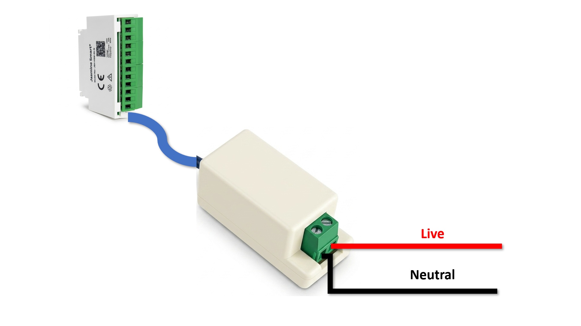
Power Adapter Integration
- Terminate the main AC Live Line (typically Red/Brown) into the input terminal labeled Live on the Power Adapter Module.
- Terminate the main AC Neutral Line (typically Black/Blue) into the input terminal labeled Neutral.
- Locate the integrated tail cable extending from the adapter.
- Insert the male quick-release connector directly into the receiving socket at the bottom of the Smart Switch Module until it clicks.
2-Way Switch Loop Wiring
Each physical switch must be a standard 3-terminal 2-way toggle switch. First, connect the main Live Line directly to the Middle (Common) terminal of all four physical wall switches.
| Channel | 2-Way Switch "Top" | 2-Way Switch "Bottom" |
|---|---|---|
| Channel 1 | Connects to Pin 1 (Top) | Connects to Pin 3 (Bottom) |
| Channel 2 | Connects to Pin 4 (Top) | Connects to Pin 6 (Bottom) |
| Channel 3 | Connects to Pin 7 (Top) | Connects to Pin 9 (Bottom) |
| Channel 4 | Connects to Pin 10 (Top) | Connects to Pin 12 (Bottom) |
Load & Appliance Termination
Connect the switched Live wire of each appliance to the corresponding channel's Middle Pin on the 12-pin terminal block.
Crucial Step: Connect all Neutral return wires from the four appliances directly to the main system Neutral Line (or common Neutral busbar in your distribution box). Only the Live path is switched through the Jasmine module!
Complete Circuit Diagrams
Reference these comprehensive diagrams to verify your connections. You can test with a single channel first, or proceed with the full 4-channel setup.
1-Channel Circuit Setup
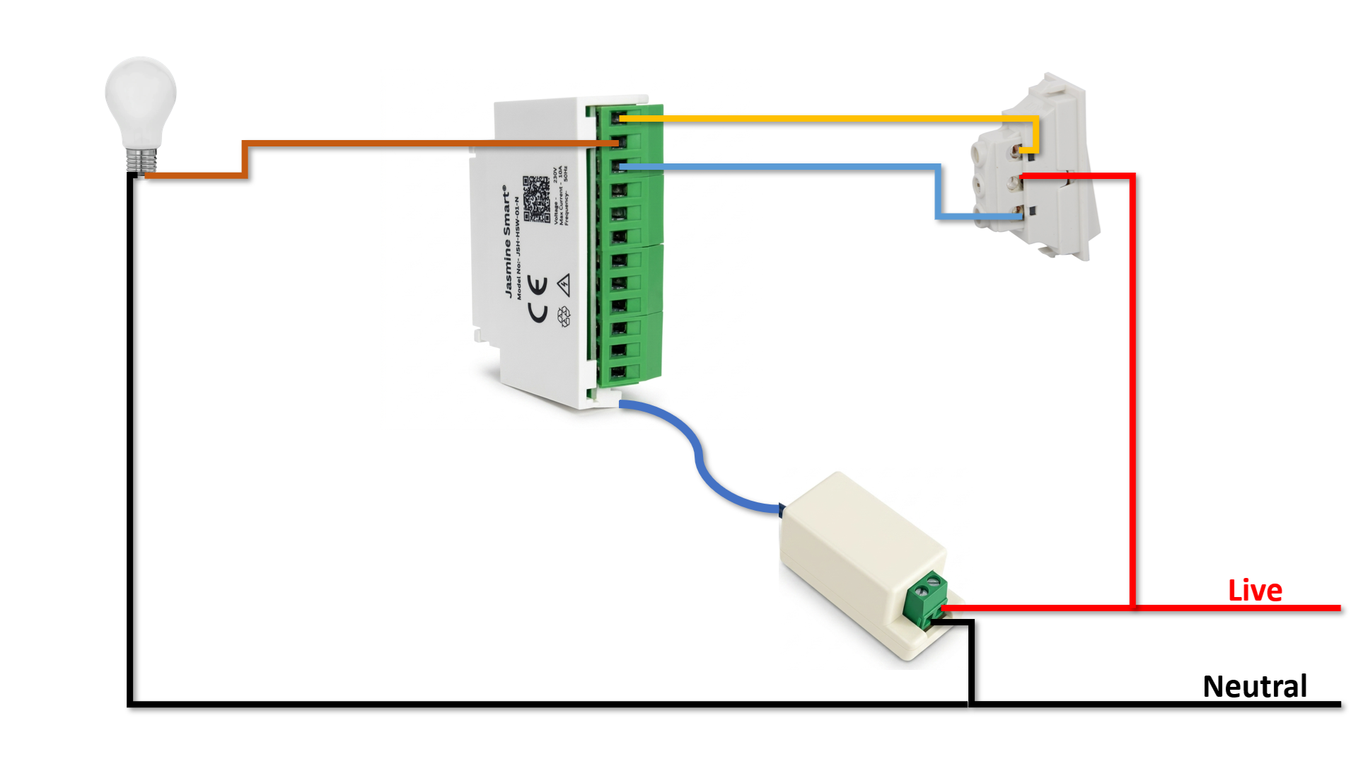
This diagram illustrates the fundamental wiring concept applied to a single appliance and switch. It's recommended to test one channel before fully securing the junction box.
Fully Connected 4-Channel Circuit
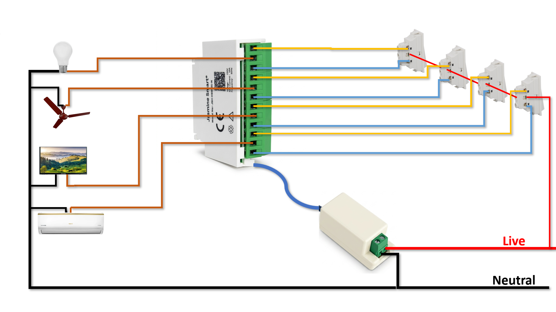
The complete configuration connecting all four appliances and wall switches. Note the shared Live line for the mechanical switches and common Neutral line for appliances.